PDM Tips

Saturday, January 21, 2006

PDM CASE STUDY

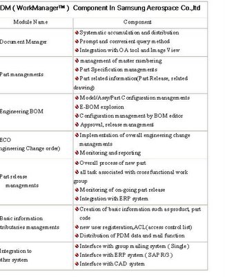
Samsung Aerospace Co., Ltd., PDM project was carried out by 3 following step implementation step.

STEP1

Overall Re engineering in whole camera developments and production division from product planning to delivering to market Streamlining cross-functional organization

STEP 2

Set up "To-Be Processing" for the best over-all efficiency and Design of PDM Detail function as Integrated Product Information System. ( PDM Vaults System with Work Manager TM )

STEP3

Applying "To-Be process" to working and Continuous maintenance for To-be process Implementation of "Workflow system" on the basics of PDM vaults system integration PDM system with ERP system ( SAP R/3 )


SHARE POINT PORTAL SERVER

SharePoint Portal Server creates a portal web site that allows users to share documents and search for information across the organization and enterprise, including SharePoint Team Services-based Web sites—all within one extensible portal interface. And, SharePoint Portal Server includes robust document management features that allow companies to incorporate business processes into their portal solution.

When implemented in conjunction with Solid Edge V11 or V12 Sharepoint Portal Server provides the framework for a Product Data Management solution encompassing; vaulted security, version control, ECO and approval routing for all Solid Edge data.

End-to-end solution
Small workgroups often get by using a combination of e-mail, file servers, and their own hard drives to store and share information. This type of information sharing has become the status quo for team information sharing because all members can participate easily and equally, but it does not create an organized record of a team’s efforts. Using a SharePoint Team Services-based Web site gives teams an easy and informal way to centralize and share project or and team information with team members and other interested parties within the organization.

At an organization or business division level, however, information-sharing requirements naturally become more sophisticated. Using SharePoint Portal Server, organizations can aggregate content from across the organization into a portal Web site so that their users can find the information they need to make better business decisions, regardless of where the data resides. This requires comprehensive search capabilities and the ability to manage large volumes of information across a great number of data stores. Business units also need advanced document management, including structured publishing processes to ensure the information they are sharing is complete and up to date.

Microsoft SharePoint Portal Server allows enterprises to effectively aggregate corporate knowledge across file servers, databases, public folders, and Internet sites as well as SharePoint Team Services-based Web sites.

Standard Features of SPPS

1) Integrated document management:-
This feature contains the following points

a) Search Engine:- Retrieve text using state of art probabilistic ranking. The search engine also features best bets, property searches and auto categorization of crawled content

b) Data access and indexing:- Crawl and search files and web servers, Microsoft exchange server public folders, lotus notes servers, and remote server for share point portal server.

c) Subscriptions:- Subscribe to a document folder, category or search query so you are notified when changes are made.

d) Categories:- Classify content under a set of customer define categories, this allows easy navigation to the information.

2) Scalable Enterprise Search

• Office and windows integration:- A complete set of document management functionality is accessible directly from the Microsoft office 2000 toolbar and Microsoft windows explorer. This helps users manage document with familiar tools.

• Check in and check out:- Enable optional enhanced web folders so individual users for updating can reserve that document.

• Document versioning:- Document changes including metadata such as keywords are tracked and assigned different version numbers for auditing and rollback.

• Document profiling:- This captures optional and required metadata about customer defined document type.

• Security:- Using roles built on Microsoft windows NT security, share point portal server ensures that only users with appropriate access can see a given document.

BENEFITS OF SPPS

Simplest access to business information
• Index the most important enterprise content sources and content types; capture and respect security settings for Windows, Exchange and Lotus Notes
• Best results from search queries based on an industry-leading probabilistic ranking algorithm
• Stay current on topics, documents and searches using subscriptions based on scalable persistent query technology
• Classify similar types of content and group it appropriately through automatic categorization technology

Seamless knowledge portal integration with the Microsoft Office and Windows productivity desktop.
• Incorporate business processes around documents with check-in/check-out, versioning and approval routing functionality
• Easily track document history and roll back to previous versions
• Effectively classify documents by applying business relevant information to each document
• Include people outside the enterprise in the document collaboration process with the web browser as an alternative user interface

The most effective way to build and extend intranet portals

• Easily extend the digital dashboard-based Tahoe portal UI by adding Web Parts
• Easily create personalized Digital Dashboards and share them with other users
• Built on Internet and industry standards such as XML, WebDAV, ADO/OLEDB and CDO
• Using Visual Studio developers can write applications that leverage Active Server Pages and ADO to add collaboration functionality

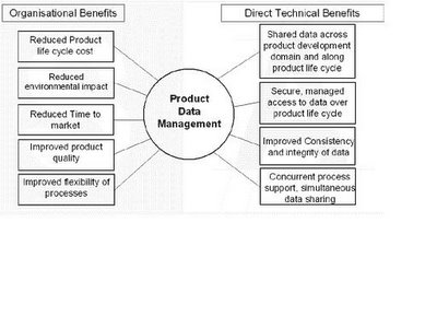
BENEFITS OF PDM


Reduced Time-to-Market

This is the major benefit of a PDM system. Three factors serve to place limits on the speed with which you can bring a product to market. One is the time it takes to perform tasks, such as engineering design, and tooling. Another is the time wasted between tasks, as when a released design sits in a production engineer's in-tray waiting its turn to be dealt with. And the third is time lost in rework.
A PDM system can do much to reduce all these time limitations.
• It can speed up tasks by making data instantly available as it is needed.
• It supports concurrent task management.
• It allows authorized team members access to all relevant data, all the time, with the assurance that it is always the latest version.

Improved Design Productivity

Product Data Management systems, when driving the appropriate tools, can significantly increase the productivity of your engineers.

With a PDM system providing them with the correct tools to access this data efficiently, the design process itself can be dramatically shortened.

Another factor is that designers should spend more time actually designing. Historically a design engineer would spend as much as 25-30% of his time simply handling information; looking for it, retrieving it, waiting for copies of drawings, archiving new data. PDM removes this dead time almost entirely. The designer no longer needs to know where to look for released designs or other data; it is all there on demand.

A third major time saver is the elimination of the 'reinvented wheel' syndrome. The amount of time designers spend solving problems that have probably been solved before, is notorious. It is often considered quicker to so it again than to track down design elements that could be re-used. With a PDM system, however, the identification, re-use and modification of existing similar designs should become routine.

Improved Design and Manufacturing Accuracy

An important benefit of PDM systems is that everyone involved in a project is operating on the same set of data which is always up to date. If you are working on a master file you know it is the only one; if you're viewing a reference copy, you know it is a replica of the latest master. So overlapping or inconsistent designs are eliminated - even when people are operating concurrently. Naturally this leads to far fewer instances of design problems that only emerge at manufacturing or QA, fewer ECOs, more right-the-first-time designs and, once again, a faster path to the marketplace.

Better use of Creative Team Skills

Designers are often conservative in their approach to problem solving for no other reason than the time penalties for exploring alternative solutions are so high. The risks of spending excessive time on a radically new design approach which may not work would be unacceptable. PDM opens up the creative process in three important ways.
• First, it keeps track of all the documents and test results relating to a given product change, minimizing design rework and potential design mistakes.
• Second, it reduces the risk of failure by sharing the risk with others and by making the data available to the right people fast.
• Third, it encourages team problem solving by allowing individuals to bounce ideas off each other using the packet-transfer facility, knowing that all of them are looking at the same problem.

Comfortable to Use

Although PDM systems vary widely in their levels of user-friendliness, most set out to operate within the existing organizational structure of a product engineering operation, without major disruption. The system should, in fact, make familiar tasks much more user-oriented than before. When users wish to view information on a PDM system, the application is loaded automatically, and then the document is loaded. In a conventional working environment, users would either have to be much more skilled at accessing the information or be prepared to accept it in a much less flexible form.

Data Integrity Safeguarded

The single central vault concept ensures that, while data is immediately accessible to those who need it, all master documents and records of historical change remain absolutely accurate and secure.

Better Control of Projects

The reason that product development projects are almost invariably late is not that they are badly planned in the first place, but that they routinely go out of control. Why? Because the immense volume of data generated by the project rapidly snowballs beyond the scope of traditional project management techniques. The greater the competitive time pressures, the greater the scope for inconsistency, and likelihood of rework. PDM systems enable you to retain control of the project by ensuring that the data on which it is based is firmly controlled.

Product structure, change management, configuration control and traceability are key benefits. Control can also be enhanced by automatic data release and electronic sign-off procedures. As a result, it is impossible for a scheduled task to be ignored, buried or forgotten.

Better Management of Engineering Change

A PDM system must allow you to create and maintain multiple revisions and versions of any design in the database. This means that iterations on a design can be created without the worry that previous versions will be lost or accidentally erased. Every version and revision has to be 'signed' and 'dated', removing any ambiguity about current designs and providing a complete audit trail of changes.

A Major Step toward Total Quality Management

By introducing a coherent set of audited processes to the product development cycle, a PDM system should go a long way towards establishing an environment for ISO9000 compliance and Total Quality Management (TQM). Many of the fundamental principals of TQM, such as 'empowerment of the individual' to identify and solve problems are inherent in the PDM structure. The formal controls, checks, change management processes and defined responsibilities should also ensure that the PDM system you select contributes to your conformance with international quality standards.

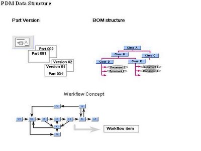
Part and Part Version

Products are made up of Parts. They consist of Parts. Some Parts may compose an Assembly, a Module or a Component. These are clusters or sets of Parts that make up the Product.

Parts are often identified by Part Number. A Part Number should normally be a non-significant number possibly prefixed with a code that identifies the Origin of the Part (where does it come from: "place of birth").
The "Item Locator" is intended to be similar an URL that can be used globally within the Extended Enterprise with all their Partners. The Item Locator consists of an Owner Domain which identifies the "owner" of the Part Number Series at their own company within the Group, the Part Number and the Part Version. The format for each of these three components will have to be decided within the enterprise.
All Parts at all levels of the Product Structure will also have a Part Version. The normal rules should be as follows:
• When a Part at a lower level changes and gets a new Part Version, this is not reflected at the next higher level.
• When a Part at a lower level changes and gets a new Part Number, this is reflected at the next higher level where the Part gets a new Part Version. Changing the Part Versions higher up through the Product Structure is not recommended and it should never be mechanized.
This is normally adequate for all industries except aircraft and possibly car industries where it may be necessary to manage parallel versions of the same Part in manufacturing. This should be recorded for each built Product Instance. When and if this is necessary, it should not be recorded in the Nominal Product/PDM application but as information related to the built Product Instance (see Life Cycles and Views).
The decision of when an engineering change affects FFF and calls for a new Part Number is a decision that should be taken by humans and not be done through mechanized rules in the application.

ADVANCED PDM SYSTEMS


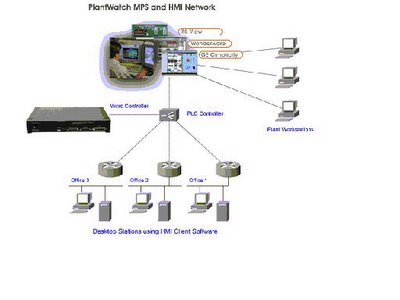
PLANTWATCH simultaneously evaluates vibration, and temperature inputs to determine machine condition with an incredible high level of accuracy.
• It is an On-Line Monitoring System with (web enabled) Remote Diagnostic capabilities.
• It is primarily used to monitor your critical plant equipment or machines in remote or hazardous locations.
• The system offers 24/7 monitoring and trending, providing you piece of mind.
• Affordability - Lowest cost in the industry
• Scalability - 8, 16, 32 channels available
• Connectivity - No server required

With over 20 years of experience in the Machinery Vibration Monitoring industry, PDM has designed the new generation PLANTWATCH system to facilitate the "much needed" and exploding "On-Line" market. With our experience and success in this field "we introduce the best solution".

How Does PLANTWATCH Work?

PLANTWATCH is a permanently mounted vibration monitoring system that give users a clear and clear and concise overview of a machines health.
PLANTWATCH is responsible for getting the key information to the decision makers "whenever" or "wherever" they are, "immediately" a problem occurs.
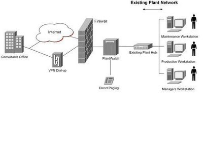
PLANTWATCH automatically transmits either an email and/or pager message describing the machine's mechanical condition.
When connected to a LAN, the PLANTWATCH will alert any workstation or control room terminal that an alarm has been breached.
The power of networking (Intranet) and the Internet, machines cannot only be monitored from your desk, but also diagnosed but anywhere in the world.
System Features:
• Simultaneous display of Displacement, Velocity, Acceleration and Temperature
• Alarm status - Green, Yellow, Red
• Baseline overview - Normal operating condition
• Trending - Data can be reviewed over several months

CHARACTERISTICS OF PDM SYSTEMS

1. Single Repository --- only one copy of any one document exists at a time, and is centralized. No more the problem of stray-copies that vary from the origin.

2. Data Vault --- the single, central location data vault provides the ideal foundation for the new characteristics of a PDM system; security.

3. Ease of Access --- some PDM systems use page locking rather than record locking, this allows access to almost any data. Some go further and allow even those pages that are locked by another user to be accessed in read-only mode.

4. Audit Trails --- an audit trail of all changes made to documents is kept within the PDM system. To assist in maintaining an accurate and secure system, PDM keeps all copies of previous revisions in an archive. This provides integrity with only one active, original document in existence at a time, while maintaining backups and traceability in the event of questions.

5. Multi-Classification --- Product data is heterogeneous in nature. for example, files can be technical publications, BOMs, text, spreadsheets, video, audio, drawings, computer models, purchase orders, etc. They are grouped by "type" in the PDM database. However, these documents are also filed by type of document, author, customer, supplier, date (created, shipped, accessed, due, etc), dollar value, file size, and other classifications. Documents are grouped and classified in multiple ways, forming a network or hierarchical tree-like retrieval structure, or a matrix.

6. Fast Retrieval --- the Multi-Classification allows fast retrieval of documents. PDM system classify data for quick identification and easy retrieval by the ERP application or by its users.
7. Attribute Handling --- Components and manufacturing assemblies can also be classified. These parts not only fall within certain categories or grouping but can have specific attributes attached to them; this was a feature that was missing from many early ERP systems. Most PDM systems today go a step further and use complex configuration-logic to add dependent and/or optionally available attributes to components. These attributes, for example, may only be available under certain conditions. An example of an optional attribute would be color; a filing cabinet comes standard in black but the customer can request it in beige, but the two-drawer cabinet may not have this option. The handling of these options was difficult logic to incorporate into earlier systems and was often not seen as necessary.

8. Revision Control and Lifecycle Management --- Document revision control is handled automatically by PDM, always allowing the user access to the latest revision. BOMs, drawings and other documents that are sensitive to change control are automatically moved between the central valid document repository and the archives. Documents, much like products, have a lifecycle. PDM systems can manage documents based on criteria specified about the class or classes into which the data fall. An example of lifecycle management of a document might be the retirement of a document based on non-active. A BOM that has not been used for five years or ten years might be considered to be obsolete and could automatically be retired by the PDM system to an archive.

9.Notification --- The function of notification is nothing but house keeping, simply letting the right person be notified at right time, which will push the project keeps moving. For example, an engineer can be notified by the PDM system that the document he sent to the engineering committee was approved and is ready for his attention.

10.Workflow Management --- Workflow management provides engineers the information needed to accomplish the next step in the process. It also allows those working on designs to have the relevant change history and interdependencies visible. Workflow provides a sandbox for an engineer to try, thousands of iterations if needed in the design process and provides a review and approval process. Peers are able to easily review and contribute to relevant design improvements, and managers are able to track the progress of a project and to provide approval upon completion. If an engineer submits a job, also known as a packet, to a peer for review, the rights to modify the packet remain with the original engineer.

11. Facilitation of Concurrent Engineering --- In PDM, not only can several engineers work simultaneously on a particular project but also multiple departments can be working concurrently the project. This feature improves time-to-market for new products.

12. Intelligent Data Retrieval --- PDM functions as an expert-system providing intelligent data because of the way it is designed and implemented.

13. Direct Material Sourcing --- DMS is a method of integrating suppliers into the product development process to produce best total cost products in quicker times. DMS tightly interfaces with the supply chain allowing purchasing, product-development, and manufacturing, to quickly and effectively track engage to supplier base; it should help leverage contracts, track sourcing history, address supply risks, and effectively analyze thousands of sourcing alternatives, and suggest optimum solutions.

14. Product Portfolio Management --- PPM is the grouping and control of all the data from multiple departments. It includes the management of engineering data, manufacturing data, purchasing data, and accounting data.

15.Customer Needs Management --- CNM is the process that PDM software uses to gather, process, track, forecast, and integrate the customers' requirements into the product procurement, design, production, and delivery. While direct materials sourcing looks at the supplier chain, CNM looks at the customer side of the supplier chain seeking to seamlessly integrate the customers' input into every aspect of the product.

System Administration

The System Administration module of the EDM/PDM system is the module that allows the initial configuration and environment of the system to be described, and the system to be set up, installed and put into use. This module will also be used to handle the changes that will occur as the environment evolves, and as the use of EDM/PDM becomes more extensive. The specifications of the initial configuration will cover the computers, storage devices, databases, networks, electronic messaging systems, applications, workstations, plotters, printers and other terminals within the EDM/PDM environment.


The System Administrator is the person who will use the System Administration module to set up, install and administer the system. This person needs a good knowledge of operating systems, database management systems, EDM/PDM, and the workings of the company.

The System Administration module helps the System Administrator identify, create, select and manage the data storage areas. Data may be stored on different devices such as magnetic tape, magnetic disk, and optical disk. The System Administrator defines the rules describing where and how different types of data will be stored. The System Administration module will be used by the System Administrator to select the most suitable automatic back-up and recovery features. The module also allows the System Administrator to choose between different options of archive management. The module will provide step by step instructions for data recovery that may be needed because of problems due to hardware, power, network, media or user error.

The System Administration module will be used to define users to the system, identify applications in the environment, and initialize project creation rights. It will be used to define the access rights to particular data files. The module will also be used to define and modify the access rights of individual users to specific data and commands.

At installation time, the module will propose default values that, if accepted, will provide a basic, running system very quickly. The System Administrator may, of course, modify these values to develop a tailored environment. The module provides a self-audit trail, showing the history of the EDM/PDM system set-up process, and the options and values that were selected. Once the system is in use, the module can provide information on system performance metrics.

Work Management

Engineers create and change data for a living. The act of designing something is exactly that. A solid model, for example, may go through hundreds of design changes during the course of development, each involving far-reaching modifications to the underlying engineering data. Often the engineer will wish simply to explore a particular approach, later abandoning it in favor of a previous version.

A PDM system offers a solution by acting as the engineer's working environment, meticulously capturing all new and changed data as it is generated, maintaining a record of which version it is, recalling it on demand and effectively keeping track of the engineer's every move.

Of course, when an engineer is asked to carry out a design modification, he or she will normally require more than just the original design and the Engineering Change Order (ECO). Many documents, files and forms may need to be referred to and other members of the design team involved, too. In a traditional design environment you would compile a project folder or dossier which the team could refer to as needed.

Current PDM systems cope with this requirement with varying degrees of success. One approach is that which emulates paper-based processes by using what are known as 'user packets'.

The packet allows the engineer to manage and modify several different master documents simultaneously as well as providing various supporting documents for reference. This approach also supports the concurrent engineering principle. For example, although only one user can be working on a 'master' design, colleagues working on the same project can be instantly notified that there is an updated master design, and reference copies of it will be made available to them in their own packets. A given packet can be worked on only by the user to whom it is logged out, but its contents can be looked at and copied by everybody with the necessary access permissions.
Workflow Management
Packets have the advantage of making it easy for team members to share meaningful groups of documents, but they are useful for another reason, too. They make it possible to move work around from department to department, or from individual to individual in logically organized bundles.

During the development of a product many thousands of parts may need to be designed. For each part, files need to be created, modified, viewed, checked and approved by many different people, perhaps several times over. What's more, each part will call for different development techniques and different types of data - solid models for some, circuit diagrams for others, FEA data for others.

As if this is not confusing enough, work on any of these master files will have a potential impact on other related files. So there needs to be continuous cross checking, modification, resubmission and rechecking. With all these overlapping changes, it is all too easy for an engineer in one discipline to be investing considerable time and effort in pursuing a design which has already been invalidated by the work someone else has done in another part of the project. Bringing order to this highly complex workflow is what product data management systems do best. In particular they keep track of the thousands of individual decisions that determine who does what next.

Most PDM systems allow the project leader to control the progress of the project via 'states' using pre-determined 'triggers' and a routing list which may vary according to what type of organization or development project is involved. The way systems differ is in how much flexibility they permit within the framework discipline. The most rigid systems are based on procedures. Every individual or group of individuals is made to represent a state in a procedure - 'Initiated', 'Submitted', 'Checked', 'Approved', 'Released'; a file or record can't move from one individual or group to the next without changing states. Some systems make it possible to give the task an identity of its own, separate from the people working on it.

For example, suppose an engineer working on a design wants to confer with colleagues as to the best way to approach the design. So long as the master model and all the associated reference files are contained in and controlled by a packet, then it is simple to pass the entire job across to any number of other people without triggering a change of state. The formal workflow procedure is uncompromised by this informal re-routing because the authority to change the file's state doesn't move around with the packet. It remains with the designated individual.

Communication within the development team is enhanced too. When packets of data and files are passed around, they can be accompanied by instructions, notes and comments. Some systems have 'redlining' capability; others even have provision for informally annotating files with the electronic equivalent of 'post-it' notes.

In other words, a process management system could be seen as a way of 'loosening up' your working environment, instead of constraining it. The challenge is how far you can allow informal teamwork and cross-fertilization to carry on and still keep overall management control of project costs and deadlines?

Most systems allow the up-to-date status of the entire task, with all supporting data, to be tracked and viewed by authorized individuals at all times.

Of course, a packet represents one task in a product development project which may consist of many thousands. Each packet follows its own route through the system but the relationship between packets also needs to be controlled.

To coordinate such a complex workflow effectively you need to be able to define the interdependence of tasks so as to match the way your individual project is structured. Not all systems are easy to customize in this way. The ones that are have the ability to create a hierarchical relationship between files. For example, you could instruct the system to prevent an engineer from signing off an assembly for release until all its parts have been individually released.

Information structure definition

The Information structure definition module is used to define the information structure and organization of a product throughout its life cycle. It defines a basic function-independent view of the product, and different functional views of the structure. The Information structure definition module is used to create the information structure of a product, and to create, by modification, the information structure of derivative product versions. It can support a hierarchy of classifications such as part, sub-assembly, assembly, component, product, and system, or segment, macro, function, and program.

The Information structure definition module is used to define which types of information are associated with each of the components of the basic structure at the various stages of the product life cycle, and to describe the relationships between information items.

.Information structure management
The Information structure management module is used to maintain and work with information structures created by the Information structure definition module. Throughout the product life cycle, it maintains the relationships between the information structure and the information items.

At each stage of the life cycle, the Information structure management module is aware of the exact state of the associated information items describing product information such as specifications, drawings, parts lists, test results, and field information. It maintains a complete history of the product through design, manufacture and delivery to field use. It is aware of the status of all information (e.g. in-process, in-review, released), and can distinguish between the as-specified, as-designed, as-built, as-installed, and as-maintained configurations of the product.

The Information structure management module supports multiple assembly levels, multiple hierarchies, multiple membership and multiple product versions, and takes account of engineering changes. It maintains information about the relationships between information such as the creation of one file from another

Interface

The Interface module is made up of four sub-modules:
• user interface sub-module
• program interface sub-module
• data interface sub-module
• information presentation sub-module
These sub-modules provide access to the EDM/PDM system for people and systems, and allow different data formats to be used in different activities.

The user interface allows people to access the system from various graphics devices such as PCs, workstations, VT 100 terminals, X-terminals, and shop-floor terminals.

The program interface sub-module supports efficient and secure on-line interaction between the various programs in the EDM/PDM environment. The environment will include many computer programs that create, store, and access or modify the various types of data managed by the system. Examples of these programs include CAD, software development, technical publication, and engineering drawing scanning systems.

The data interface sub-module provides efficient and secure data exchange and data translation functionality for data that may be either in the EDM/PDM environment or outside it. For example, the EDM/PDM system may be managing data files on a CAD system and on a structural analysis system. If the data on the two systems is compatible, the data interface sub-module may be used to transfer data from the CAD system directly to the structural analysis system. If the data is not compatible, the data interface sub-module may be used to translate the CAD data to a suitable format, and then transfer it to the structural analysis program. The data interface sub-module should provide a set of translators, some standard (e.g. IGES or STEP), and some direct.

The information presentation sub-module offers report generation facilities for screen, file and paper reports. They should be tailorable to fit user requirements, and user-programmable for special cases. Users will want reports on subjects.

NINE BASIC COMPONENTS OF AN EDM/PDM SYSTEM

There are nine basic components of an EDM/PDM system. The first of these is the Information warehouse in which engineering information is stored.
The Information warehouse is managed by the Information management module. This is the second component of the EDM/PDM system. It controls and manages the information in the warehouse. It is responsible for functions such as data access, storage and recall, information security and integrity, concurrent use of data, and archival and recovery.

The EDM/PDM system requires a basic Infrastructure of a networked computer environment.

Users and programs access the system through the Interface Module. This provides a standard, but tailorable, interface for users. The Interface Module supports user queries, menu-driven and forms-driven input, and report generation. It provides interfaces for programs such as CAD and ERP.

The structure of the information and processes to be managed by the EDM/PDM system is defined by the Information and Workflow Structure Definition Modules. The workflow is made up of a set of activities to which information such as resources, events and responsibilities can be associated. Procedures and standards can also be associated with activities.

The exact structure of all information in the system is maintained by the Information Structure Management Module.

Once initiated, workflow needs to be kept under control. This is the task of the Workflow Control Module, which controls and co-ordinates the engineering process. It manages the engineering change process and provides revision level control.
The ninth component of the system is the System Administration module. The complete system is under its control. It is used to set up and maintain the configuration of the system, and to assign and modify access rights.

The Information warehouse
The role of the Information warehouse module is to store engineering data. Other names for the warehouse are Electronic Library, Electronic Vault, Information Vault, and Data Repository.

The Information warehouse acts as a single source of all engineering information in the company. This does not mean that the information has to be physically centralized. In practice it will nearly always be physically distributed, with some of the information being in different departments of the company, and some with suppliers and customers.

The Information warehouse contains all sorts of engineering information describing the products and parts such as engineering drawings, CAD data, circuit layouts, flow charts, test results, Bills of Materials, field data and word-processed product specifications. There will be information such as NC programs and technical manuals describing the processes used to design, manufacture and support the product. There will be information describing international, national and company-specific standards. There will be information describing the computer programs used in the various processes, and there may even be copies of these programs in the warehouse. There will be project-specific and order-specific information starting perhaps with the contract, and including project time and cost estimates, and actual times and costs.

The Information warehouse will contain information about information. There will be lists of drawings, parts and configurations. There will be descriptions of more complicated relationships such as those between the activities of a particular project to fulfill the requirements of a particular customer order. There will be information such as Engineering Change orders, describing changes to information in the warehouse.

Information Management
Engineering data is kept in the Information warehouse, a logical store of all engineering information on all media at all locations - centralized and distributed. The Information management module controls access and input to the Information warehouse.

The Information management module controls the input and output of data to and from the Information warehouse. It works in a multi-vendor distributed computer environment, and is able to control access to different types of data such as text files, CAD geometry, engineering drawings, and numeric results of technical calculations. It manages data in simple files, and in hierarchical, relational and object-oriented databases. The data can be in private databases (single-user), project databases (multi-user, linked to individual projects) and product databases (multi-user, describing parts and components).

The module uses metadata (data describing data) to manage data. Most of today's EDM/PDM systems are based on relational database management systems. Only the metadata (containing characteristic information about the underlying data, such as file name, type of data, author, location, access rights, version number, cost, date and other attributes), a small part of the engineering data, is stored in the relational database. The underlying engineering data is stored in the system where it was created.

The Information management module is aware of the various stages of the life cycles of the different information types. It knows how they are created, how they are used and modified, how they are stored, and how they are archived. It knows the possible release and revision levels of documents, and the steps they go through to be signed-off, released and changed.
The module is aware of the potential users of the system. Typical users include design engineers, drafters, manufacturing engineers, shop floor workers, project managers, cost analysts, and procurement staff. Users may be in different functions or at different locations of the company, or on supplier or customer sites. The module is aware of the activities and privileges of each user. It can handle situations where users have more than one activity, and where users have different roles on different projects.

The Information management module has complete control over access to the Information warehouse. It uses access rights to control user access to information items throughout the various stages of product and project life cycles. Access rights allow access to be controlled by a variety of criteria such as user, product, project, group, device, type of information, and state of information. Different access rights can be assigned to a user for activities such as creation, selection, view, modification, release, report, translation, archival, and communication of information.

The module is aware of all information in the warehouse, all activities that can be carried out on the information items, all users of the system, and the rights of all users to carry out particular activities. As a result it can control access to all information in the system. The Information management module allows users with suitable authorization to check individual files or sets of files into the warehouse, and to check them out. Sets of files may be related by different parameters such as document type, product, and user.

The Information management module is responsible for the security of information in the system. Security can be applied at different levels and on different categories such as per-user, per-information item, per-activity, or per-product. The module only provides access to authorized users, and refuses access to unauthorized users. It provides security information on any unauthorized attempts to access data. The module can provide an audit trail of all actions taken on data. The audit trail can show who has accessed and changed both data and metadata.
The Information management module is responsible for the integrity of the warehouse. It prevents multiple simultaneous update of information. It informs users of copies of information when master data or metadata has been modified, and can send them up-to-date copies. The module can manage the back-up and archival of data. It can recover any information lost as the result of computer or human problems.

The module can use metadata items as search criteria. It can search for the existence, location and status of particular information on the basis of pre-defined classification codes and characteristics such as physical properties, manufacturing processes, and part numbers. It can use metadata items for information browsing and navigation.

The Information management module can maintain distribution lists based on its knowledge of the users of the system, and the documents in the system. The lists can be dependent on specific characteristics such as current project status.

Infrastructure
The Infrastructure module provides the basic system functionality for the EDM/PDM system to operate in a multi-application, networked, heterogeneous computer environment.

Typical engineering environments include all sorts of computers, file servers, workstations, X-terminals, PCs and other graphics and alphanumeric terminals from many vendors. There will be a variety of operating systems, some of which will be proprietary. Others will be more-or-less standard versions of DOS and UNIX

The environment will probably include a wide range of application packages and in-house developments for order processing, parts management, configuration, MCAE, CAD, ECAE, ERP, document scanning, electronic publishing, structural analysis, process planning, project management, word processing, and field support
In the typical environment, there will be a variety of peripherals such as scanners, printers, plotters, shop-floor terminals and data storage devices. Much of the electronic data will be on simple files, but some could also be in hierarchical or relational databases (such as INFORMIX and ORACLE), or in other engineering data management systems. The information and its users will be distributed over different departments, different sites, and perhaps different companies.

Servers and workstations will probably be connected by WANs (Wide Area Networks) and LANs (Local Area Networks) so that information can be communicated both between sites and on-site. There will probably be links to the Internet, Intranets and the Web. There may be electronic links to suppliers. Both long 'files' and short 'messages' will have to be communicated on the networks. A file transfer of a CAD model to a supplier may involve the transfer of several MB of data. Many EDM/PDM systems rely heavily on electronic messaging to inform interested parties that a particular 'event' has occurred, and that work on the following task should now be started. For example, a message could inform a supervisor that a design has been completed and can now be released. Such messages may only be a few words long. Notifications through electronic mail ensure that everybody who needs to be aware of what is happening receives the information, and that everybody is involved in a timely fashion. In this way, when it is not possible to physically co-locate all members of a project team, the system helps create a virtual team
INTRODUCTION TO PDM SYSTEMS

An 'EDM/PDM system' is a computer-based system that helps manage engineering data and engineering activities. Such systems are known generically as Engineering Data Management (EDM) systems. Within the generic class of EDM/PDM systems are many types of systems such as those known as Product Data Management (PDM) systems, and those known as Engineering Document Management Systems (EDMS)?


EDM/PDM systems do several things. They manage engineering data and provide improved management of the engineering process through better control of engineering data, of engineering activities, of engineering changes and of product configurations. EDM/PDM systems also provide support for the activities of product teams and for techniques, such as Concurrent Engineering, that aim to improve engineering workflow.


EDM/PDM systems treat engineering information as an important resource that is used by many functions in a company. They allow companies to get control of engineering information, and to manage activities in several departments. In the long term, EDM/PDM systems will allow companies to get control of all their engineering information, and manage the overall engineering process. These characteristics set EDM/PDM systems apart from systems such as CAD that aim to improve the productivity of individual tasks in one functional area. Viewed as data processing systems, EDM/PDM systems go beyond individual application programs such as CAD and NC. Viewed as organizational tools, they go beyond individual approaches such as DFA (Design for Assembly) and project management systems.


EDM/PDM systems provide a backbone for the controlled flow of engineering information throughout the product life cycle. Other systems using engineering data, such as CAD, ERP and field service, will be integrated to this backbone. EDM/PDM systems address both information and workflow issues. As such they are true integration tools. In particular, within the engineering environment, they are central to the integration of previously separated systems such as CAD, CAM, CSM, Electronic Publishing, Configuration Management, Process Planning, Document Scanning and Project Management. Their use will result in improved quality, flow and use of information related to the engineering process. This will help companies meet the growing demands of an ever more competitive business environment.


EDM/PDM systems address issues such as control, quality, reuse, security and availability of engineering data. Much as CAD, CAM and CAE were important in the 1970's and 1980's, EDM/PDM will be key to successful engineering in the 2000's and beyond. EDM/PDM systems offer important new functions for the engineering environment. They will help solve many of the problems that beset today's engineering environment, and for those who master them, will offer new strategic opportunities

Thursday, January 19, 2006

Reordering Offset Cross-Sections

Sometimes you find its necessary to reorder the placement of an Offset Cross Section. For instance when you want to reroute the cross-section through other components (assembly) or other features (parts) which were placed after the offset cross-section was created.

The problem with Pro/E is (upto R2001) that these Offset cross-sections are created as Internal Suppressed Cosmetic Features. There is no way to determine its internal ID or to show them in your Model Tree. So you can't select them for reordering to the end of your part for instance.

Here is a workaround to do this:

Determine which feature is immediately before the x-sect. You can do this by redefining the cross-section #modify; 'x-sect'; #redefine; #section) then look at the last feature in the Model Tree.
Now enter the insert mode selecting the previous found feature as the feature to insert after. Verify that the offset x-sect is suppressed by attempting to show it. If it's name is unavailable or if it's not shown then you are at least in front of the X-section.
Create a temporary feature like a coord-sys or datum plane with references only to features early in the feature list, like the default dtm planes or c-cys.
Cancel insert mode.
Reorder all the following features by range (don't select your temp. feature), and reorder them only before the temporary feature you just created.
Delete the temporary feature.

TIP:Leave the feature there for future reference. It could function as a pointer to your offset cross-section which is right behind it. Rename it accordingly.
Verify if it was successful by choosing #modify, 'x-sect', #redefine. Then look at the model tree to see that the x-sect is after the last feature.